tailgate Ram 1500 2013 Get to Know Guide
[x] Cancel search | Manufacturer: RAM, Model Year: 2013, Model line: 1500, Model: Ram 1500 2013Pages: 196, PDF Size: 9.66 MB
Page 3 of 196

INTRODUCTION/WELCOME
WELCOME FROM CHRYSLER
GROUP LLC.................. 3
CONTROLS AT A GLANCE
DRIVER COCKPIT .............. 6
INSTRUMENT CLUSTER .......... 8
GETTING STARTED
KEYFOB ................... 10
KEYLESS ENTER-N-GO™ ......... 11
REMOTE START .............. 13
THEFT ALARM ............... 13
SEATBELT .................. 13
SUPPLEMENTAL RESTRAINT
SYSTEM (SRS) — AIR BAGS ....... 14
CHILD RESTRAINTS ............ 15
FRONT SEATS ................ 20
HEATED/VENTILATED SEATS ....... 22
HEATED STEERING WHEEL ........ 23
TILT STEERING COLUMN ......... 24
OPERATING YOUR VEHICLE
ENGINE BREAK-IN
RECOMMENDATIONS........... 25
TURN SIGNALS/WIPER/WASHER/
HIGH BEAMS LEVER ............ 26
HEADLIGHT SWITCH ............ 27
SPEED CONTROL .............. 28
EIGHT–SPEED AUTOMATIC
TRANSMISSION — IF EQUIPPED .... 29
ELECTRONIC RANGE SELECT (ERS)
OPERATION ................. 30
AIR SUSPENSION SYSTEM ........ 32
MANUAL CLIMATE CONTROLS
WITHOUT TOUCH-SCREEN ........ 34
MANUAL CLIMATE CONTROLS
WITH TOUCH-SCREEN ........... 35
AUTOMATIC CLIMATE CONTROLS
WITH TOUCH-SCREEN ........... 36
PARKSENSE
®REAR PARK ASSIST . . . 37
PARKVIEW®REAR BACK-UP
CAMERA ................... 38
TIRE PRESSURE MONITOR SYSTEM
(TPMS) – 2500 MODELS ONLY ...... 38
POWER SLIDING REAR WINDOW .... 39
POWER SUNROOF ............. 40
WIND BUFFETING ............. 41
ELECTRONICS
YOUR VEHICLE'S SOUND SYSTEM . . . 42
IDENTIFYING YOUR RADIO ........ 44
Uconnect
®Access (AVAILABLE ON
Uconnect®8.4A AND Uconnect®8.4AN)
(IF EQUIPPED) ................ 45
Uconnect
®3.0 ................ 54
Uconnect®5.0 ................ 56 Uconnect
®8.4A ............... 62
Uconnect®8.4AN .............. 79
STEERING WHEEL AUDIO
CONTROLS .................. 97
ELECTRONIC VEHICLE
INFORMATION CENTER (EVIC) ..... 98
PROGRAMMABLE FEATURES ....... 98
UNIVERSAL GARAGE DOOR OPENER
(HomeLink
®) ................ 101
POWER INVERTER ............ 103
POWER OUTLETS ............ 104
OFF-ROAD CAPABILITIES
FOUR WHEEL DRIVE OPERATION . . . 105
UTILITY
TONNEAU COVER............. 108
EASY-OFF TAILGATE ........... 108
PICKUP BOX ................ 109
RAMBOX
®.................. 110
TOWING & PAYLOAD ........... 114
TOW/HAUL MODE ............ 116
INTEGRATED TRAILER BRAKE
MODULE .................. 116
RECREATIONAL TOWING
(BEHIND MOTORHOME, ETC.) ..... 118
DIESEL
DIESEL ENGINE BREAK-IN
RECOMMENDATIONS........... 120
DIESEL ENGINE STARTING
PROCEDURES ............... 120
DIESEL EXHAUST BRAKE
(ENGINE BRAKING) ........... 121
IDLE-UP FEATURE (AUTOMATIC
TRANSMISSION ONLY) ......... 122
ENGINE MOUNTED FUEL
FILTER/WATER SEPARATOR ....... 123
UNDERBODY MOUNTED FUEL
FILTER/WATER SEPARATOR ....... 124
ADDING FUEL – DIESEL ENGINE
ONLY ..................... 125
EXHAUST REGENERATION ....... 125
COOL-DOWN IDLE CHART ........ 127
DIESEL EXHAUST FLUID ........ 127
WHAT TO DO IN EMERGENCIES
ROADSIDE ASSISTANCE......... 130
INSTRUMENT CLUSTER WARNING
LIGHTS ................... 130
IF YOUR ENGINE OVERHEATS ..... 134
JACKING AND TIRE CHANGING .... 135
JUMP-STARTING ............. 148
EMERGENCY TOW HOOKS ....... 150
SHIFT LEVER OVERRIDE ........ 150
TOWING A DISABLED VEHICLE .... 153
FREEING A STUCK VEHICLE ...... 154
EVENT DATA RECORDER (EDR) .... 155
TABLE OF CONTENTS
Page 12 of 196

KEY FOB
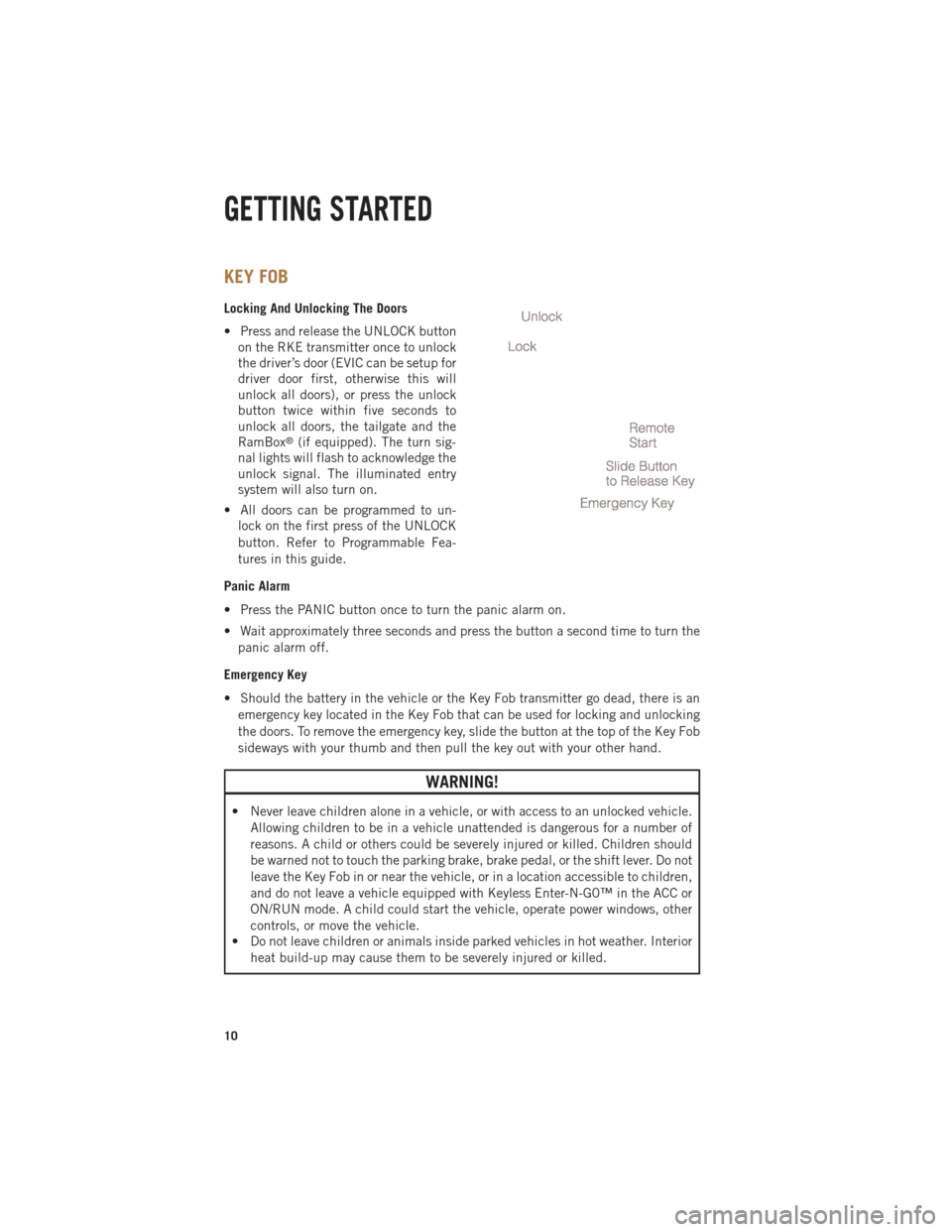
Locking And Unlocking The Doors
• Press and release the UNLOCK buttonon the RKE transmitter once to unlock
the driver’s door (EVIC can be setup for
driver door first, otherwise this will
unlock all doors), or press the unlock
button twice within five seconds to
unlock all doors, the tailgate and the
RamBox
®(if equipped). The turn sig-
nal lights will flash to acknowledge the
unlock signal. The illuminated entry
system will also turn on.
• All doors can be programmed to un- lock on the first press of the UNLOCK
button. Refer to Programmable Fea-
tures in this guide.
Panic Alarm
• Press the PANIC button once to turn the panic alarm on.
• Wait approximately three seconds and press the button a second time to turn the panic alarm off.
Emergency Key
• Should the battery in the vehicle or the Key Fob transmitter go dead, there is an emergency key located in the Key Fob that can be used for locking and unlocking
the doors. To remove the emergency key, slide the button at the top of the Key Fob
sideways with your thumb and then pull the key out with your other hand.
WARNING!
• Never leave children alone in a vehicle, or with access to an unlocked vehicle. Allowing children to be in a vehicle unattended is dangerous for a number of
reasons. A child or others could be severely injured or killed. Children should
be warned not to touch the parking brake, brake pedal, or the shift lever. Do not
leave the Key Fob in or near the vehicle, or in a location accessible to children,
and do not leave a vehicle equipped with Keyless Enter-N-G0™ in the ACC or
ON/RUN mode. A child could start the vehicle, operate power windows, other
controls, or move the vehicle.
• Do not leave children or animals inside parked vehicles in hot weather. Interior
heat build-up may cause them to be severely injured or killed.
GETTING STARTED
10
Page 40 of 196

PARKVIEW® REAR BACK-UP CAMERA
• You can see an on-screen image of the rear surroundings of your vehicle wheneverthe shift lever is put into REVERSE. The ParkView®Rear Back-Up Camera image
will be displayed in the rearview mirror or touchscreen display along with a caution
note to “check entire surroundings” across the top of the screen. After five seconds
this note will disappear.
• If the rearview mirror or touchscreen display appears foggy, clean the ParkView
®
camera located to the left of the tailgate handle.
WARNING!
Drivers must be careful when backing up; even when using the ParkView®Rear
Back-Up Camera. Always check carefully behind your vehicle, and be sure to
check for pedestrians, animals, other vehicles, obstructions, or blind spots before
backing up. You must continue to pay attention while backing up. Failure to do so
can result in serious injury or death.
TIRE PRESSURE MONITOR SYSTEM (TPMS) – 2500 MODELS
ONLY
Tire Light Load Inflation Switch Description
•
The Tire Pressure Monitoring System on your vehicle has two different tire pressure
settings based on vehicle loading. The Tire Light Load Switch is located on the
Instrument Panel below the climate controls.
• The “Light Load Inflation” and “Max Load Inflation” tire pressures recommended for your vehicle based on vehicle loading are found on the Supplemental Tire
Pressure Information Label located on the rear face of the driver front door.
•
When the vehicle is in the “Light Load Inflation” setting, the Tire Light Load Inflation
switch is On. The indicator light is Off when in the “Max Load Inflation” setting.
Light Load Inflation (Indicator Light On)
• If the passenger and cargo weights are less than the Light Load Pressure Definition shown on the Supplemental Tire Pressure Information Label, inflate or
deflate tires to the correct “Light Load Inflation” pressure. If the indicator light is
not on, the mode can be changed by pushing the switch once.
• If the light on the switch flashes On and Off, after the button is pressed to switch
between modes, this indicates conditions are not correct to switch modes. The system
will not allow switching modes until the tire pressures have been set to Light Load
Inflation as indicated on the Supplemental Tire Pressure Information Label.
OPERATING YOUR VEHICLE
38
Page 110 of 196

TONNEAU COVER
• The Tonneau Cover can be removed and reinstalled by using the locking clampslocated underneath the Tonneau Cover.
NOTE:
Be sure that the Tonneau Cover is secured before driving.
EASY-OFF TAILGATE
•To simplify mounting of a camper unit with an overhang, the tailgate can be removed.
NOTE:
If your vehicle is equipped with a rear camera or RKE the electrical connector must
be disconnected prior to removing the tailgate.
Removing the Tailgate
• Disconnect the wiring harness for the rear camera or RKE (if equipped).
• Unlatch the tailgate and remove the support cables by releasing the lock tang from the pivot.
• Raise the right side of the tailgate until the right side pivot clears the hanger bracket.
• Slide the entire tailgate to the right to free the left side pivot.
• Remove the tailgate from the vehicle.
NOTE:
Do not carry the tailgate loose in the truck pickup box.
Locking Tailgate
• The lock is located next to the tailgate handle. The tailgate can be locked using the vehicle key.
WARNING!
To avoid inhaling carbon monoxide, which is deadly, the exhaust system on vehicles
equipped with “Cap or Slide-In Campers” should extend beyond the overhanging
camper compartment and be free of leaks.
UTILITY
108
Page 114 of 196

Divider Position
• There are 11 divider slots along the bed inner panels which allow for variouspositions to assist in managing your cargo.
• To install the bed extender into a divider position perform the following: • Make sure the center handle is unlocked using the vehicle key and rotate thecenter handle vertically to release the extender side gates.
• With the side gates open, position the extender so the outboard ends align with the intended slots in the sides of the bed.
• Rotate the side gates closed so that the outboard ends are secured into the intended slots of the bed.
• Rotate the center handle horizontally to secure the side gates in the closed position.
• Lock the center handle to secure the panel into place and assist against theft.
Extender Position
• The bed extender will add an additional 15 in (38 cm) in the back of the truck when additional cargo room is needed.
• To install the bed extender into the extender position, perform the following: • Lower the tailgate.
• Make sure the center handle is unlocked and rotate the center handle verticallyin order to release the extender side gates.
• Fit the end of the side gate ends onto the pin and handle.
• Rotate the handles to the horizontal position to secure into place.
Bed Rail Tie-Down System
• There are two adjustable cleats on each side of the bed that can be used to assist in securing cargo.
• Each cleat must be located and tightened down in one of the detents, along either rail, in order to keep cargo properly secure.
• To move the cleat to any position on the rail, turn the nut counterclockwise, approximately three turns. Then, pull out on the cleat and slide it to the detent
nearest the desired location. Make sure the cleat is seated in the detent and
tighten the nut.
• To remove the cleats from the utility rail, remove the end cap by pushing up on the locking tab, located on the bottom of the end cap. Slide the cleat off the end of the
rail.
UTILITY
112
Page 115 of 196

CAUTION!
• Failure to follow the following items could cause damage to the vehicle:• Assure that all cargo inside the storage bins is properly secured.
• Do not exceed cargo weight rating of 150 lb (68 kg) per bin.
• Leaving the lid open for extended periods of time could cause the vehiclebattery to discharge. If the lid is required to stay open for extended periods
of time, it is recommended that the bin lights be turned off manually using
the on/off switch.
• Ensure cargo bin lids are closed and latched before moving or driving
vehicle.
• Loads applied to the top of the bin lid should be minimized to prevent
damage to the lid and latching/hinging mechanisms.
• Damage to the RamBox
®bin may occur due to heavy/sharp objects placed
in bin that shift due to vehicle motion. In order to minimize potential for
damage, secure all cargo to prevent movement and protect inside surfaces
of bin from heavy/sharp objects with appropriate padding.
• The maximum load per cleat should not exceed 250 lbs (113 kg) and the
angle of the load on each cleat should not exceed 60 degrees above
horizontal, or damage to the cleat or cleat rail may occur.
WARNING!
•Always close the storage bin covers when your vehicle is unattended or in motion.
• Do not allow children to have access to the storage bins. Once in the storagebin, young children may not be able to escape. If trapped in the storage bin,
children can die from suffocation or heat stroke.
• In a collision, serious injury could result if the storage bin covers are not
properly latched.
• Do not use a storage bin latch as a tie down.
• To reduce the risk of potential injury or property damage:
• Cargo must be secured.
• Do not exceed cargo load rating of your vehicle.
• Secure all loads to truck utilizing cargo tie-downs.
• Extender should not be used as cargo tie-down.
•
When vehicle is in motion do not exceed 150 lbs (68 kg) load on the tailgate.
• The bed extender is not intended for off road use.
•
When not in use, the extender/divider should be in stowed or divider position
with the tailgate closed.
• When in use, all handles are to be in the locked position.
UTILITY
113
Page 138 of 196

2500/3500 Series Trucks
• Remove the jack and tool bracket assembly by removing the wing bolt and slidingthe jack and tool bracket assembly from under the seat.
Removing The Spare Tire
• Remove the spare tire before attempting to jack up the truck. Attach the wheel wrench to the jack extension tube. Insert the tube through the access hole between
the lower tailgate and the top of the bumper and into the winch mechanism tube.
Rotate the wheel wrench handle counterclockwise until the spare tire is on the
ground with enough cable slack to allow you to pull it out from under the vehicle.
When the spare is clear, tilt the retainer at the end of the cable and pull it through
the center of the wheel.
NOTE:
Always stow the spare tire with the valve stem facing the ground.
1. Wheel Wrench
2. Spare Tire
• It is recommended that you stow the flat or spare to avoid tangling the loose
cable.
NOTE:
The winch mechanism is designed for
use with the jack extension tube only.
Use of an air wrench or other power tools
is not recommended and can damage the
winch.
WHAT TO DO IN EMERGENCIES
136
Page 188 of 196

AUTHENTIC ACCESSORIES BY MOPAR®
• The following highlights just some of the many Authentic Ram Truck Accessoriesby Mopar featuring a fit, finish, and functionality specifically for your Ram Truck.
• In choosing Authentic Accessories you gain far more than expressive style, premium protection, or extreme entertainment, you also benefit from enhancing
your vehicle with accessories that have been thoroughly tested and factory-
approved.
• For the full line of Authentic Ram Truck Accessories by Mopar, visit your local Ram Truck dealership or online at mopar.com.
CHROME:
• Exhaust Tip • Tubular Side Steps • Fuel Filler Door
• Cast Aluminum Wheels • Front Air Deflector • Grille
• Body Side Molding
EXTERIOR:
• Bedliners • Running Boards • Fender Flares
• Composite Tonneau Cover • Bed Extender • Bed Mat & Bed Rug
• Roll-up Tonneau Cover • Bed Step • Tool Box
• Folding Tonneau Cover • Hitch Receiver •
Sports Performance Hood
• Molded Splash Guards • Tailgate Lock • Body Kit
INTERIOR:
• Premium Carpet Mats • Door Sill Guards • Slush Mats
• Ambient Light Kit • Bright Pedal Kit • Heated Seats
ELECTRONICS:
• Kicker
®Sound Systems • Electronic Vehicle Tracking • Remote Start
• Mopar Wi-fi
CARRIERS:
•
Bed Mounted Bike Carrier• Bed Mounted Cargo Basket With Cargo Net • Cargo Ramps
• Bed Mounted Ski and Snowboard Carrier • Cargo Bed Divider
• Kicker®is a registered trademark of Stillwater Designs and Audio, Inc.
MOPAR ACCESSORIES
186
Page 191 of 196

SIRIUS Travel Link...........89
SparkPlugs..............162
Speed Control (Cruise Control) ....28
Starting Cold Weather ...........121
Remote ...............13
Starting Procedures (Diesel Engines) ..........120
SunRoof ................40
Tailgate ................108
Temperature Control, Automatic(ATC)...........36
Theft System Arming ..........13
Theft System Disarming ........13
Tires Air Pressure ...........182
Changing .............137
FlatChanging ..........137
Jacking ..............137
Pressure Monitor System
(TPMS) ...............38
Pressure Warning Light .....130
Tow/Haul................116
Tow Hooks, Emergency ........150
Towing Disabled Vehicle .........153
Recreational ...........118 Towing Vehicle Behind a
Motorhome .............118
Trailer Towing Trailer and Tongue Weight . . .114
Transfer Case Fluid ................162
Transmission Fluid ................162
WarningLight ..........133
TurnSignals...............26
Uconnect
®3.0.............54
Uconnect®5.0.............56
Uconnect®8.4A ............62
Uconnect®8.4AN ...........79
Ventilated Seats ............22
Washers, Windshield ..........26
Water in Fuel .............120
WheelandWheelTrimCare.....182
Wheel Cover ..............144
WheelNutTorque...........144
Wind Buffeting .............41
Windshield Washers ..........26
Windshield Wipers ...........26
INDEX
189